


The Hydraulic Reservoir
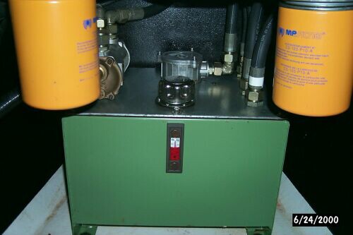
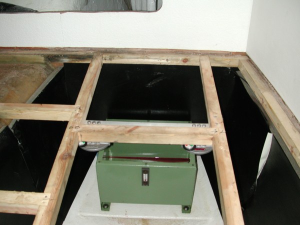
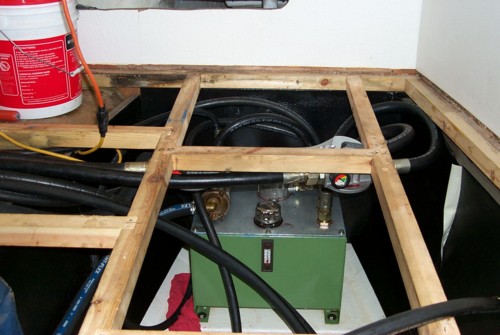
Here is a picture of the space underneath the master bedroom bunk of our Prout Escale. Clearly visible is the green hydraulic oil reservoir with the two orange main suction filters in front of it. Since the system was designed and assembled in Europe, all fittings and filters are metric, so we always keep next years supply on hand... delivery times can be long! The tank also features a heat exchanger to keep the oil cool (mounted on top of the tank, to the left). This heat exchanger basically "pre-heats" the raw engine water. Once we replace the undersized hoses in the system, there should be less friction, "singing" and heating.
Mounted on each filter is a pressure element that gives us an idea of how clogged they are. However, no filter has ever encountered the 500 hour life that the elements are good for. The wall behind the hydraulic oil tank is the bulkhead that separates the bedroom from the rear crash compartment. When that compartment flooded due to the heater hatch leak, the water seeped forward into this space. The water contaminated the hydraulic oil and so the entire system had to be dismantled, cleaned, and reinstalled.
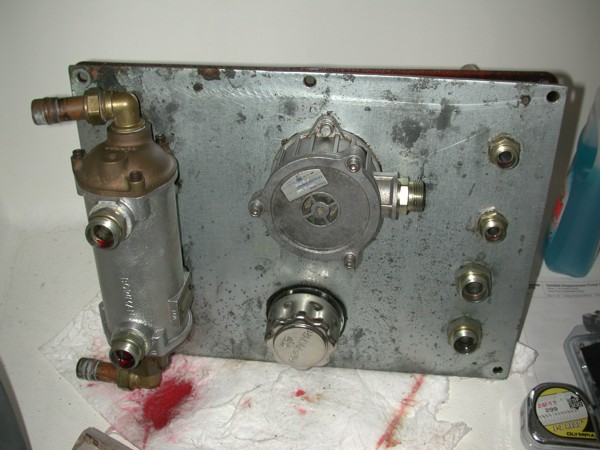
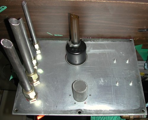
The hydraulic oil heat exchanger is to the left. The cap in the bottom middle section is where oil is added while the assembly above it is a filter unit for the charge-pump returns. The four ports on the side are split between charge pump suction and motor bypass return. Everything looks fine from the outside...
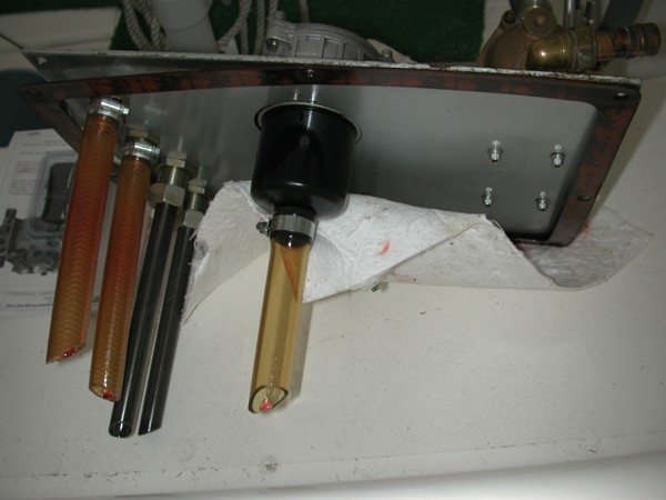
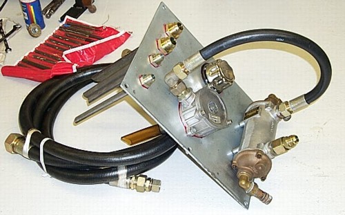
...now look at the underside of the plate. The motor bypass lines as installed were ¼" OD and led to the ¾" braided PVC lines you can see below. Relatively\little fluid is supposed to run inside this set of hoses, hence their small diameter.
Fluid requirements in the suction lines are much larger (about 5 GPM each at 4,000 RPM). Since the suction lines are supposed to have little pressure drop, they tend to have larger OD's than even the lines connecting the pumps to the motors. As acknowledged by Mr. Bechler at the hydraulic design bureau, the suction lines were already too small as installed (¾").
The installers at Prout Catamarans compounded the problem by marrying ½" intake lines underneath the tank cover (hard black plastic lines behind the bypass hoses) to the ¾" suction lines above. The pressure drop due to such a narrow intake is likely to negate any benefit that even the ¾" lines had. If we hadn't caught this error now, imagine our likely subsequent consternation about performance inhibition despite installing larger suction hoses! This sort of error is not the kind of problems you expect intelligent people to create.
Diagnosing this sort of screw-up is difficult at best unless you take the whole system apart and look at all the links, even the ones that logic dictates you shouldn't have to. The hose mismatch was invisible to us since it was hidden under the lid of a tightly sealed container. If anything else, this is a pretty good hint not to do anything at the Prout factory that could be remotely construed as "custom". Furthermore, don't trust your intuition or anything for that matter. When it comes to Prout Catamarans, trust is nice but verification is better!
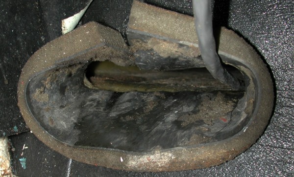
Here we have a pass through for the hydraulic lines. The cable to the right will be relocated shortly and with some hope, the newer, thicker hydraulic lines will still fit. Otherwise, we'll enlarge the hole. Piece of cake, as long as the engine isn't in the way.
To remove the hydraulic lines we had to remove the floor under each bunk. Note the interesting lattice work of wooden beams. In the picture above, our port frames are rotting to the top left, a legacy of past water ingress. The hydraulic oil tank below is missing its top while the two screw terminals for the suction oil filters are visible above.
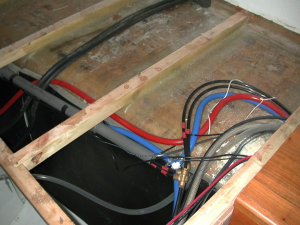
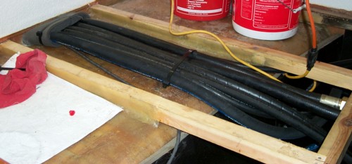
In the picture below, some additional lines are visible under the starboard bunk. The twin lines running to the top right of the picture are for the heat exchanger. The red and blue lines below distribute cold and hot freshwater throughout the boat. The small black OD hose runs to the hydraulic steering ram in the back of the boat as well as the hydraulic pump for the autopilot.
Year 2002 Update: The new hoses have arrived!
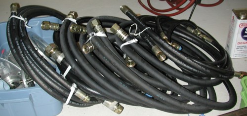
Our new hydraulic hoses feature the same pressure capabilities as the ones they replace even though our system will never attain them. For example, the pumps should be set to a maximum of 2,400 psi before cutting out, yet the A&B hoses have a maximum working pressure of 4,000 psi. This safety margin should make our system pretty leak proof.
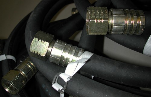
We had to keep track of a number connectors...
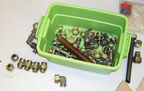
The new lid for our hydraulic oil reservoir:
Our hydraulic reservoir lid has also seen a renaissance. Besides sporting new terminals throughout to accommodate the larger hoses that will be attached to it, it also has proper interior tubing, and a much larger hose connecting to the heat exchanger. Note how the tube diameter difference has changed places from the "before" picture.
All of a sudden, the large ID tubes are at the bottom, not the top of the left hand side. The picture is on its head to keep the perspective the same as in the "before" picture. In the picture below, the tank lid has a more isometric appearance.
Our new hydraulic hoses needed a wider bed in order to accomodate their larger outer diameters.
The system around the tank looks a bit like spaghetti. However, we knew everything would fit since we had the previous hoses to take to the hydraulics shop for replacement. Working with the larger OD's was simply more tiring as they resist bending more and are harder to wrestle into place.
Note the hose exiting the tank to the right, then running into the filter element (w/o the customary orange MP Filtri Catridge) before making for the pump (towards the left). The blue-lined raw water hose can be seen to the lower left. It feeds the hydraulic oil cooler before continuing its journey to the engine. Once all connections had been made, we put the bunk mattress surfaces back into place. A oil re-fill and circulation later, the hydraulics system was ready for action.
Best Estimate of time Spent fixing hydraulic tank and lines
| Dismantle rest of hydraulic system | 4 hours |
|---|---|
| Obtain new hoses | 6 hours |
| Rebuild inside of tank | 6 hours |
| Install new hoses, refill system w/hydraulic fluid, flush | 8 hours |
| Test system | 1 hour |
| Total | 25 hours |
|---|