How to Repair a Broken Base Station:
Early in 2001, my loyal Base Station at home gave up its ghost and started to cycle endlessly (red light at left, 3 amber, rinse, repeat). My unit was out of warranty, Apple told me they would not replace it, and I did not feel like spending another $300 unless I had to. Hence, I investigated what led to the early death of my base station. The repair was much cheaper and easier than I thought...
These repair instructions should also help owners of similar wireless base stations manufactured by Lucent technologies (AP-500, RG1000, and RG1100). The motherboards inside these Lucent units look exactly the same as the ones found in Airport base stations. Click this link for an image of the guts of a RG1000. HP apparently also uses this motherboard for the HP 802.11b Wireless LAN Small Business Access Point.
For an riveting read about the background of these capacitor failures, have a look at the following IEEE article. It is alleged that botched Taiwanese industrial espionage caused the rash of capacitor failures. Is it coincidence then, that the first version of Graphite ABS' sport Taiwanese-made Lelon capacitors, while repaired (or later) Graphite ABS' have Japanese-made Sanyo capacitors? This Toronto Star article describes similar failures with ABIT motherboards for PCs... Japanese capacitors manufacturers are sure to be happy, now that component buyers are once again willing to pay 4x more for Japanese versus Taiwanese-manufactured capacitors...
Furthermore, these sorts of capacitor failures are not limited to Lucent, Apple, or ABIT gear. For example, Benjamin Feist encountered the same sort of problem in a 3COM HomeConnect 10/100 5-port ethernet hub and has posted similar repair instructions (i.e. find dead capacitors and replace them). I guess we should consider ourselves lucky: According to this thread at Slashdot (Thanks Benjamin!), capacitors failures have been known to result in everything from explosive failure to outright fires.
However, your first strategy should be to get Apple to replace the unit rather than repair it yourself.
- If your base station is broken but still under warranty, get on the phone at once and get a replacement sent to you. When you call (In the US: 1-800-275-2273), select technical assistance (option 1), then option 3 (thanks Rick Tom Greever).
- If you bought an Apple laptop with an extended service plan, the base station is covered as a "peripheral", regardless of when you bought the base station. AppleCare telephone support people may not know this, but confirm it once they check, so if they say no, insist politely... (thanks Raúl Vera)
- Some credit card companies automatically double the warranty coverage of products you bought with their credit cards (typical of "Gold" and above).
- Apple used to replace broken, out-of-warranty base stations with like models under a semi-secret program that initially only covered units in the serial number range from PW940... to PW952.... Unfortunately, Drew Robison at Apple wrote to me in July 2003 to tell me the replacement program has been discontinued.
The informal Graphite replacement program was never publicized and was only described in a Apple-internal document (Knowledge Base Article #111785). Replacement units were refurbished base stations that, while functional, could be in pretty sorry shape aethestetically. While the program has apparently ended, it might still be worth a try to call Apple Customer support.
John Endahl writes that his replacement ABS contains SANYO capacitors and that its serial number starts with PW123... . These capacitors have a rated life of 5,000 hours... in theory good for at least a couple of years. Rick Getchell posted pictures and specifications of the new power supply with its OS-CON and AL-E series capacitors on his web-site. At its apex, the exchange program appeared to apply world-wide. However, success depended on the contact person on the Apple side. Sadly, it's little wonder that litigious and/or strong consumer protection environments like the US, Canada, and the UK were the first geographies to be covered by this informal exchange program.
Anyway, if your base station is not covered by Apple or other warranties, the following repair instructions may be of use to you. Note however, that whatever warranty you had is history once you open the unit.
Please remember that the following information is for educational/entertainment purposes only. I make no guarantees that my repair instructions will work for you. Furthermore, you have to be somewhat knowledgeable about electronics to properly extract and replace the components. The work involves hot soldering irons, tight working quarters, and could quite possibly hurt you or someone else. You could also damage a component inadvertently, disable your ABS, even cause a fire.
In other words, this information is provided for your use at your own risk.
If you are not competent and experienced enough to make these repairs yourself, go and find someone in a Hi-fi repair shop to do them for you (it will be at a reasonable cost compared to buying a new ABS). My first ABS took me two hours to fix, the second one twenty minutes (including the ventilation modifications described here). I am a manufacturing engineer by training and have relatively little soldering experience (though I am very good at burning my fingers!). Therefore, a fair number of people should be able to execute these repairs at home without problems (the 1000+ thank-you e-mails I have received overwhelm the 10 or so problem reports). Here is a excellent link on good soldering practices suggested by Bruce Hubbert.
I know of several online resources that offer ABS repairs in case you don't feel like doing the job yourself and do not have a local hi-fi/electronics repair facility.
- Tech Superpowers in Boston, MA repairs ABS' for $99 with shipping and a 60 day warranty. They'll give you $50 for your ABS if they can't repair it.
- Base Station Rescue is a service that offers to repair broken base stations for $50 with shipping and with a 90 day warranty. If they can't repair your ABS, then they'll refund most of the charges. You can even elect to have them fit your ABS with an external antenna. However, there seem to be some issues with the operator of this business, as several readers have been disappointed by them.
- Base Station Repair offers a even less expensive service at $60 with shipping and a one year warranty. They even offer a $7 kit for those who want to repair the ABS themselves. The kit includes 4 capacitors, solder, and braid, and it may be cheaper to order the kit from them than to order the components yourself.
- Ipes in Germany also offers repairs if Apple won't replace the base station. (Thanks Thomas Noy!)
- In Denmark, you can contact Andy Vestergård who offers to repair the ABS for 300 dkr.
- In Japan, Jonathon Fletcher reports that the fine folks at Pucebaboon also do a fine job of repairing base stations for $35.
If you chose to let someone else repair your ABS, please let me know how it went!
If you still want to repair the ABS, please read the instructions in their entirety. If you understand every step of the way, the repair should be pretty quick. If you have any questions, or anything is unclear, please use the e-mail address at the bottom of this page to contact me. Start by creating a good working environment with the following hand tools and supplies:
- A big clear table with nearby wall outlets
- 15W soldering iron with a fine tip (Radio Shack #64-2051 or equivalent)
- Fine solder (Radio Shack #64-026 or equivalent)
- Desoldering braid (Radio Shack #64-2090 or equivalent)
- Rosin soldering flux (Radio Shack #64-021 or equivalent)(Thanks R. Chang!)
- Wire snips (to cut the tips off replacement capacitors once seated)
- Small Phillips screwdriver for base station screws
- Small flat-head screwdriver to assist with telephone plug removal
- Needle-nose pliers to pull capacitor legs with during desoldering.
- Some safety glasses to wear during the repair
- At least two replacement capacitors (more on that below)
- Optional: A digital multimeter that can measure resistance (an ohmmeter)
- Optional but a good idea: Grounding strap - wear this whenever you handle the motherboard.
Here we have a range of capacitors you might want to consider.
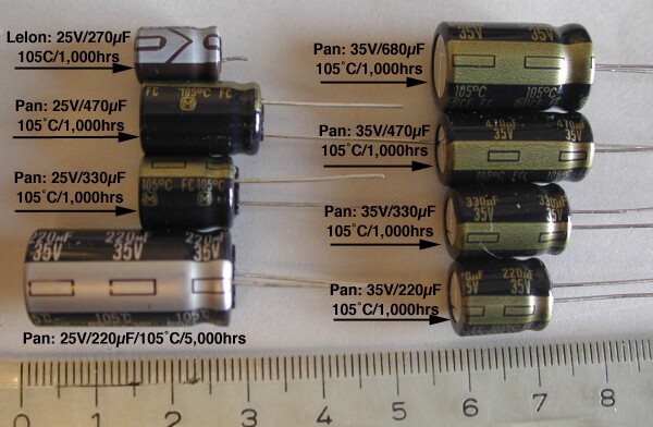
In the top left corner is a leftover OEM capacitor (Lelon brand). Notice the puny size and the slight bulge at the top - a sure sign it is fried. Below it are two 25V Panasonic FC series capacitors followed by a rather large 220µF Panasonic HF series capacitor at the bottom. In the right column are four 35V Panasonic FC series capacitors. Centimeter scale.
Note the size differences. Evidently, the higher the voltage rating or capacitance, the larger the capacitor. However, why then is the 220µF HF series capacitor much bigger than the 220µF FC series capacitor of the same voltage rating?
The simple answer is that the HF series is supposed to last between 3,000 and 5,000 hours under 105°C conditions, while the FC series gets by with 1,000 hours. Naturally, if you go with other capacitor technologies (tantalum, other $$$ forms of electrolytic caps) form factors change. But for our purposes, reliability, voltage rating, and capacitance have a direct effect on the size of capacitor.
- If you go with Radio Shack capacitors, I'd buy two 220µF electrolytic capacitors (#272-1029). However, I fear the Radio Shack components won't last very long enclosed in an ABS due to their low temperature rating (85°C) and suspect electrical qualities unless you retrofit ventilation.
- Seth Stroh has designed similar power supplies and suggested substituting readily available 330µF, 25V, 105°C Panasonic FC series capacitors (Panasonic part number EEU-FC1E331 - thanks Lars Hoel). You'll need two and can buy them at Digikey in the USA (part number P10273-ND) or other fine electronic component sources such as RS Components in Germany (Thanks Holger Eiboeck). In the UK, Nick Harvey recommends ordering the Panasonics at www.rswww.com (part number 315-0568). The Panasonic capacitors are larger than the Lelon ones but will fit and are suitable for use inside an enclosed ABS. David Chatton recommends Elko 220uf 25V capacitors which can be ordered under part# 801803 at Distrelec in Switzerland. In Germany, Conrad seems like a pretty good source for 330µF (P/N B41851) and 220µF (P/N 472522) capacitors (Thanks Silvio Martin and Andre Spiegel!) Thomas Noy notes that Neumerkel in Germany also carries Elko capacitors.
- Apple now uses Sanyo capacitors in their ABS'. Thus, if you want to recreate the current Apple configuration, here are the two capacitors you want to order: Sanyo OS-CON 20SH68M (C51 - left Cap - 68µF) and Sanyo AL-E 16MV220AX (C52 - right Cap - 220µF). They have a rated life of 5,000 hours at 105°C. More info about the capacitors from Sanyo at their OS-CON and AL-E capacitor web-sites. (Many thanks to Rick Getchell and Alexander Traud!) You can find equivalent capacitors at Newark Electronics under the Sprague name 20V-68µF = Sprague P/N 94SA686X0020EBP, 10V-220µF = Sprague P/N 94SA227X0010FBP. United Chemi-Con markets theirs with the following part numbers: 20FH68M and 10FH220M. (Many thanks Tim Degraye!) Chris Valentine found 220µF 25V Rubycon capacitors (stock # 580-480) at Farnell.
- For those that want to use high-tech Tantalum capacitors, Brent Jones recommends 10µF Tantalum capacitors that are available from either Radio Shack or Digikey. Such capacitors are apparently the best choice with the type of power supply found on the motherboard of a Graphite ABS.
- There is really no point in trying to replace the blown capacitors with like models since they don't seem to work too well. For the sake of history, here are their specifications: Lelon Industries RXJ series type 927L, 270µF, 25V, 105°C, low ESR (impedance), about 6mm wide, 10 mm long)
Initially, I installed the Radio Shack capacitors while I waited for the Panasonic replacements from Digikey. They worked fine and since I didn't need the base station to look pretty, this fix worked for me. However, in the interest of helping folks that want to reassemble their base stations completely, I yanked the Radio Shack capacitors back out and installed the 330µF Panasonic capacitors mentioned above. Here then the updated step by step instructions. They worked for me and perhaps they'll work for you too. Please read all instructions before you make any permanent modifications.
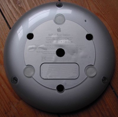
Disconnect the base station from all external cables (power, ethernet, phone). Undo the three screws on the bottom, take off bottom plate (see picture below)
Plug the power supply back into the base station, listen, but don't touch the components. If you are suffering from the same failure mode as I did you might hear a hissing sound. If the sound is there, you have a pair of damaged capacitors. Some readers had internal power supplies so dead that the supplies made no sound at all.
Next, undo the three screws that hold the inner carrier inside the base station:
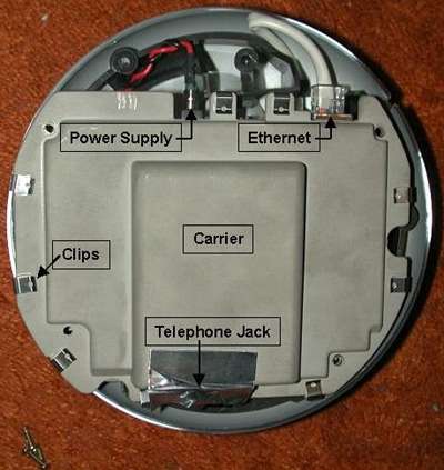
Carefully disconnect the power and ethernet connectors on the top. The power supply plug simply pulls out of the motherboard connector. The ethernet plug has a "catch" like a phone plug that you'll have to depress before you can pull it out.
A bit trickier is the removal of the phone connection under the silver tape at the bottom of the carrier. While the plug has no catches or other retaining devices, it can jam against the carrier when you try to pull it out. Here, a small flathead screwdriver can work wonders to guide the white plug past the protruding lip of the carrier.
Now you can extract the carrier (the gray thing in the middle that has all those metal clips around the perimeter) by sliding it out in the direction of where the telephone jack used to be connected. The telephone jack is pretty flat and can be hard to disconnect (the carrier can get in the way) so using a fine-tipped flat-head screwdriver can help to push the carrier just enough out of the way to make pulling the plug a little easier.
Here is a further diagnostic:
Disconnect the power supply and extract the WaveLAN card on the underside. Now plug the power supply directly into the power jack on the carrier and see if the LED's go through their usual startup "dance" before settling into the green phase. Some readers power supplies were so dead that they didn't even make it into this phase. However, with any luck you'll note a lack of a hissing sound once the WaveLAN card is removed.
In my case, the base station booted flawlessly and was even available via the admin manager if the ethernet was plugged into the ethernet jack on the carrier. Thus, I knew that the inability of the base station to fulfill its task was not related to the FlashROM - it was a power supply problem. The hissing noise and the failure mode returned once I reseated the WaveLAN card. From the 800+ messages I have received so far, only one or two were from people with fried FlashROMs. Thus, the dominant mode of failure seems to be a internal power supply failure.
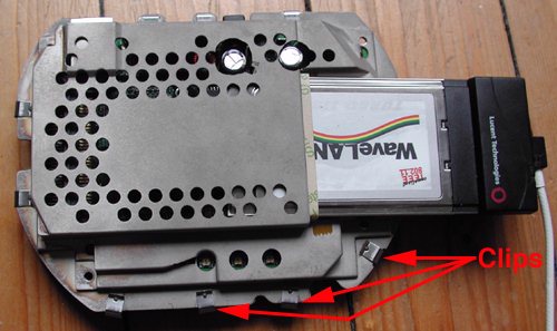
Undo all connections (power, etc.) and extract the WaveLAN card. Then undo the metal clips around the perimeter of the carrier and set them aside. Open the carrier and extract the motherboard. This picture shows the optional extender antenna sticking out of the WaveLAN card. A new base station will not have this, see the range extender part of the web-site for more info on how to add one.
Once all the clips are removed, you can lift off the top carrier piece. Below, you will see the motherboard in all its glory. Try to ground yourself before handling it, as even minute static charges can damage it. The best method is to wear a grounding strap. The next best way is to ground yourself before touching the motherboard. One way to do this is to touch a radiator or other grounded object that has a exposed metal skin. However, you have to do this without having to travel back to your workstation. Otherwise, you may build up static charge along the way.
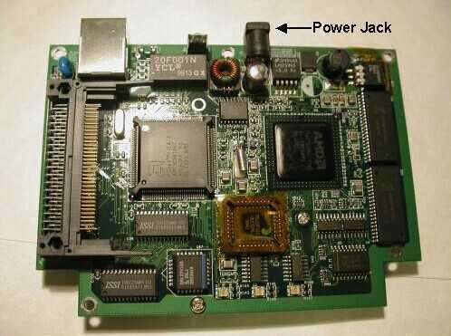
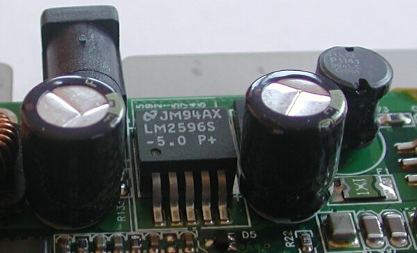
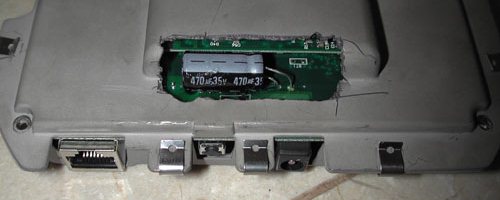
Here we have the motherboard, powered by an AMD processor. Our area of interest is at the top of the board, right around the power supply jack. Under it you will find a 270µF capacitor, to the right a LM2596S-5 voltage regulator, and to the right of that another 270µF capacitor (which had been removed by the time I took this picture - note the half-filled circle).
The two OEM capacitors were bulging at the top. Even though they are rated for 105°C use, the OEM capacitors had been cooked to death. According to the National Semiconductor literature for the voltage regulator, one should use capacitors that have a low Equivalent Series Resistance (ESR). The 150 kHz switching frequency of the power supply does not help and requires the use of higher voltage capacitors than one would normally employ.
The two 270µF capacitors that came on the board are rated for use with 25 Volts but National Semiconductor recommends at least 35V tolerant capacitors. Trouble is, the higher the volt rating of a capacitor, the larger the body. As you can see, there is very little space left on the top of the board.
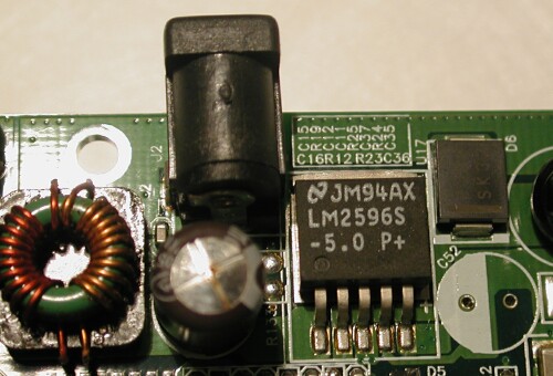
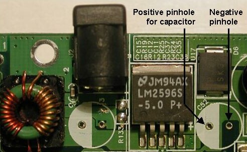
Here a close-up of the power supply with an inductor to the left, followed by the power jack and the C51 capacitor. To the right of those you can see the voltage regulator. In the top right corner is a diode while the empty circle under it outlines the missing C52 capacitor (removed).
The trick is to remove both capacitors and replace them with equal if not superior capacitors. I used a rocking motion to weaken the capacitors until they separated from their legs. Thus, when it was time to de-solder, I wasn't trying to heat the capacitor too (which is a great heat-sink).
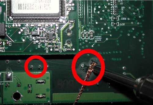
After pulling off the capacitor bodies, start on the back and remove as much of the solder around the protruding capacitor pins as you can. Take care not to de-solder the wrong pins! The correct pins are circled in red on this picture. Place the braid on the corner where the pin meets the board, then press the hot soldering iron into this corner. Change the braid 2-3 times before attempting to pull the pins out. Take care not to burn anything, including yourself.
After de-soldering as much as you can, yank the capacitor legs out with a small tool while heating from the other side. Now de-solder the holes individually, as even minute amounts of solder will prevent you from inserting a new capacitor. Patience is a virtue, but don't heat the board too much or you might damage it. Use 5 seconds max. per touch with a 15W soldering iron, less for more powerful soldering irons. Garreth Richards and others recommend you heat up a pin with which to remove leftover solder from inside the holes. If you have a drill press, a really steady hand, and very small drill bits you could even drill the solder out of the hole.
Now you can repopulate the board with new capacitors. I bought my first set at Radio Shack because I didn't want to wait for an online shipment from Digikey. However, the advantage of online merchants over Radio Shack is the variety of components you have access to. For example, Radio Shack stores do not carry 270µF, 25V, 105°C capacitors.
Initially, I looked at the data sheet for the voltage regulator and decided to substitute a 470 µF capacitor on the Vin side (C51), while going down to a 220µF capacitor on the Vout side (C52). This allowed me to buy standard components at Radio Shack and this arrangement mimics a published steady state power supply diagram in the National Semiconductor literature for testing the regulator.
A number of readers commented that dual 220µF capacitors seemed to work fine. The subsequent decision by Apple to substitute 68µF and 220µF capacitors (albeit of a higher quality and cost) allows me to endorse the use of 220µF capacitors. Ideally, go out and buy the best caps you can find the first time so you won't have to repair the ABS again. If the capacitors are mounted from underneath (i.e. with their legs sticking up in the pictures above) larger capacitors will fit. Otherwise, go for the Panasonic, Sanyo, or equivalent capacitors which can be mounted easily in the same spot and with the same orientation. Mounting the capacitors from above, makes it harder to get the polarity wrong. Polarity is very important, as you'll otherwise fry the capacitors in no time.
Interestingly enough, Apple decided to replace the two capacitors with units from Sanyo that had very different capacitances. The 20V rated input capacitor has a capacitance of 68µF instead of 270µF. The output capacitor has a even lower voltage rating of 16V and a capacitance of 220µF. According to Brian Whitaker, Apple could chose these capacitance values because the "brick" external power supply used by Apple actually has a float voltage of 12.4VDC while the output voltage from the voltage regulator shouldn't rise above 6VDC. Thus there was no need for capacitors with a 25V voltage rating. Furthermore, the power drain on the downstream side is so steady that once again no capacitors with "high" voltage ratings (as per the National Semiconductor documentation which has to assume the worst) were necessary.
However, equally interesting was the choice of Apple to use a 12VDC external supply with a 5VDC regulator inside the ABS. According to Hac Da Le, no component inside the ABS uses 12VDC. So, the more adventurous among you could convert the base station to run off 5VDC, thus removing several points of failure, and allow the base station to run cooler. However, such work is beyond the skills of most people, so I cover it only on the power-supply discussion page. We speculate that the 12VDC path that Lucent chose has to do more with the potential features they wanted to offer with one mostly-common motherboard.
For example, powering the ABS via a ethernet cable (PoE = Power over Ethernet) is a feature that Lucent offered in its virtually identical AP500 for a very high premium. Interestingly, Airport Extreme Base Stations now feature 5.1VDC external power supplies. Perhaps they learned their lesson...
Anyway, let's get then to repairing your ABS.
Clean the replacement capacitor legs with alcohol, then coat them with a very thin layer of rosin solder flux. The flux sucks the solder into the hole, ensuring a good electrical joint. Stick the capacitors into their respective holes and take care to ensure polarity. On the electrolytic capacitors I used, a minus "-" sign on one side was a good clue which side of the capacitor belonged into the ground hole (see picture above). Otherwise, have a look at the leg length... the longer leg is the positive one on the Panasonics and all radial capacitors I know. Orientation is important as the capacitors will fail in a few minutes if they are inserted incorrectly.
After successfully substituting the 470µF and 220µF capacitors, my shipment from Digikey finally came in. Since I wanted to demonstrate a solution that allows you to close the ABS back up again (and, as you may recall, the 470µF Radio Shack capacitor is too tall to allow this if mounted in the same spot as the original caps), I yanked the Radio Shack capacitors back out again, and substituted the 330µF, 25V, 105°C FC series Panasonic capacitors instead.
Here is a close-up of the new Panasonic capacitors in place. I have soldered them only from the backside of the motherboard but the connection seems to be strong, and this allows the lowest profile possible. While the use of 35V capacitors would have made the ABS more robust when it comes to the switching power supply currents, the 35V version of the FC series capacitors would have been too large to fit within an enclosed ABS with the capacitors facing "up" like this.
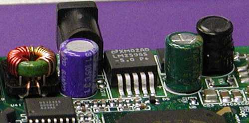
Here is a picture of the Apple replacement capacitors. The 68µF capacitor (Vin) is mounted on the left, while the 220µF Vout capacitor is to the right of the voltage regulator. (picture credit: Rick Getchell, used w/permission)
One reader suggested mounting the capacitors on the underside of the motherboard, as a greater clearance exists below. He claimed his 45V rated capacitors fit without problems once the bottom half of the carrier was modified to allow them to poke through.
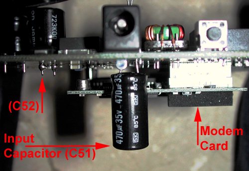
Here is an example of a underside capacitor mounting just to show how to do it. The left capacitor is a standard 220µF Radio Shack model, while the right is 470µF. Both are rated at 35V and 85°C so you'll want to ventilate the ABS. The power plug can be seen above the 470µF capacitor with the reset button to the right and the modem daughter-card below.
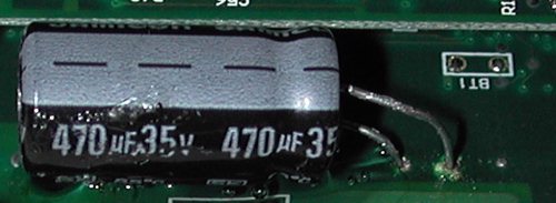
I bent the leads and the capacitor to lie on its side. The modem card edge can be seen on top of the picture. I then added glue to ensure that the capacitor could not rub against the underlying board and short out over time. Note: using two 220µF capacitors works great so there really isn't any need to resort to such mounting techniques. I just have them here for your viewing pleasure.
I had to cut a fairly large hole into the carrier to accommodate the large capacitor. Now there is no way that the unit still meets emissions or FCC requirements. But as you can see, I could have used even larger capacitors without hitting anything. The carrier hole is crude because I had no access to my tools while at my in-laws. Hence also the Radio Shack capacitors instead of Panasonic.
A benefit of mounting the capacitors below the motherboard is that they are further away from the hot voltage regulator (particularly if you choose to retrofit some ventilation holes). However, the modem card produces a lot of heat and you may consider removing it unless you have a dialup connection. The base station functions fine without the modem if it is hooked up via the ethernet port to broadband or an internal LAN.
Another reader soldered insulated wires to the holes and placed the capacitors elsewhere within the ABS. However, the technical notes for these sorts of power supplies ask for leads to be as short as possible. Thus, while a number of options exist for capacitor placement, the best one is probably to replace the broken ones in your ABS with drop-in replacements (Panasonic, Sanyo, etc.)
On with the instructions: Clean off the excess rosin flux with alcohol and cotton swabs, snip off the protruding capacitor legs within 0.25" on the other side of the board, and test. There are two tests, one of them with a multimeter, the other is more simple. The multimeter test is optional since it will be quite apparent if the ABS is functional or not. However, the multimeter test does warn of potential shorts and bad soldering jobs before they affect your ABS.
The multimeter test requires a digital ohmmeter. Place the leads on the protruding legs of the capacitors and observe the resistance. What you should see is a increasing resistance on one capacitor, decreasing resistance on the other. However, most importantly, the reading should NOT be zero OR infinity. Anything in between (as long as it increases, decreases) is OK.
The second test is more straightforward. Plug in WaveLAN card, then the power supply. If everything went right and the capacitors you replaced were faulty, the hissing noise should be gone and the LED's should go through their usual power-on sequence. Next, unplug the power, insert the ethernet, and reinsert the power plug. After boot-up, use the administrative tool to see if the base station is behaving itself, and if so, congratulations! Time to unplug everything and reassemble the base station.
Unlike the Radio Shack components, the Panasonic capacitors do not stick their heads outside the plastic enclosure. However, they are tall enough to warrant the holes you see here so that you can close the carrier w/o bulging it a little.
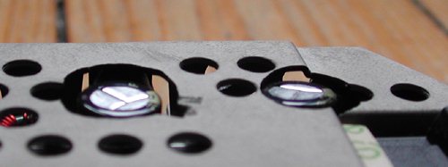
The capacitors after 6 months of continuous use - flat and happy!
Here is another view of the reassembled carrier. As you can tell, I went a little hog-wild with the dremmel tool. Ideally, no dremmeling would be required, as I imagine the carrier exists to shield the innards from stray radiation. Thus, the smaller the holes, probably the better. Also note that the carrier is quite conductive. Thus it is important to clean off the carriers and remove all burrs and shavings or they might short out your motherboard.
Now reassemble the carrier with all the thru-holes matching up, particularly if you don't intend to reassemble the ABS for heat reasons. Otherwise, you might short out the power supply or some other component. This is also the reason for cutting off the protruding capacitor legs fairly close to where they exit the motherboard (see paragraph above).

Now test the ABS for operational stability. Plug your ethernet jack back into the ABS and insert the power plug. The ABS should boot up with the usual parade of lights before settling on the familiar green center LED. If your ABS does not, there are three potential causes. Try to fix them in the following order:
- The firmware got corrupted. Here are my tips on how to reset the base station to is factory default settings. If a reset does the trick, simply upload the latest firmware and configure the unit.
- If a reset does not cure your problems, your WaveLAN card may have gone bad. The only way to test this is to get another WaveLAN card and swap it for the unit in the ABS. If the replacement WaveLAN card does the trick then you can simply buy a used one on eBay for about $25. (Thanks Keith Bhajat!)
- If the ABS boots fine after the repair with the power supply attached directly to the carrier assembly but not once it has been re-assembled, see below for further damage that can occur when the ABS power supply goes bad.
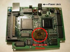
- Lastly, you may have a loose chip on the motherboard. For some reason this chip (circled red in the picture at right) may become loose or have corroded contacts. As shown, it typically is covered with yellow/orange kapton foil. If the chip is not flush with the bottom of the die it rests in, then carefully push it back into position. You can carefully extract it with a small screwdriver, working from its corners.
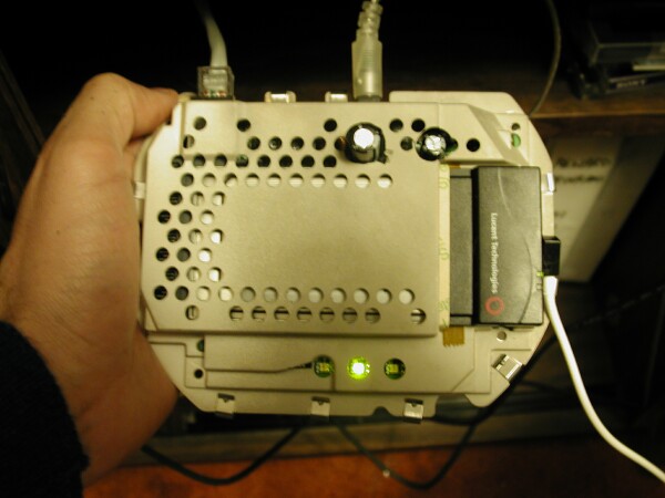
Here is a picture of the repaired base station in operation.
For several months I didn't have to use the modem in the base station and thus elected to leave the carrier outside the base station and facing up like in the picture above. That way the electronics benefit from much better cooling than inside the ABS (even with vent holes), which will prolong the life of all components in the carrier. From what I can tell, two of the three boards that interface the exterior ports in the plastics with the motherboard in the carrier are not necessary.

If you do put the exterior plastics back together, please remember to line up the "Reset Finger" with the "reset" pinhole in the bottom half of the plastics. The screw hole to the right is the "top"screw hole for the bottom exterior plastics in all the disassembly images at the beginning of the article. If you want to go on to the next project and retrofit ventilation holes also, click here.
Further Damage that can result when the power supply fails:
James Sokoll kindly sent along this tidbit of information showing how a power supply failure can do more than just cause the capacitors to bulge and explode. In fact, it can lead to other components like the F1 choke to burn out. So, if a capacitor repair doesn't bring your ABS back to life but you still feel like experimenting further, take a look at the following information. Alternatively, you can bypass the choke by plugging the ABS directly into wall wart.
Thank you for a most comprehensive and useful article. I'm from Australia, and have been involved in hardware design and maintenance for a considerable time. My contribution here may help those who have replaced the capacitors as described in this article, but the ABS is still dead-no lights at all. I had a dead ABS, (no lights), so I first checked the DC continuity. There was an open contact between the DC IN socket and the pins on the main circuit board.
I applied power directly to the main board, and got the light pattern described here. So I went back to the cause of the open contact. I removed the middle PCB behind the front panel-this board is the one which the DC IN plug connects to. This board is shown in the attached image. (below, ED)
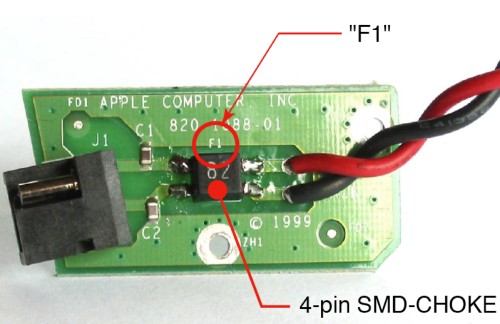
Picture of card from top of ABS
It had a 4-pin SMD component, labelled "F1". Thinking that "F1" would be a fuse in a SMD package, I thought this would be easy to fix, so I removed it. The part number shown was not readily known, so I turned the component over, only to find that it was indeed a choke-two windings, wound bifilar, on a small toroid. One of the winding was open (burnt out). I was going to replace this device with two Pico fuses (the ones like a small resistor), but as I had some small winding wire, I decided to repair it. The wire is 0.15 mm diam (0.006inch), enamelled. Ten turns are required. I don't think the diameter matters much, but don't go too far over, as there is limited space on the toroid.
Now for the next part. The fact that the wire was burnt out worried me-too much current somewhere. It was at this stage I searched the web looking for a user manual to describe the light patterns etc., when I came across your excellent article. On removing the main board, I found the two culprit caps, both with extended ends. They obviously failed and caused excessive current to be drawn. Several have contributed to the reasons for this cap failure, and have added valuable info to this discussion.
It has been my experience that excessive temperature is usually the main culprit-this causes the electrolyte to dry out, followed by a loss of capacitance, and eventually arcing, and then a short circuit. I think the voltage rating is OK, but the 85°C temperature rating of these caps, and the poor ventilation is the root cause of the problem.
The modem
The modem used in this ABS is the same as that used in the G3 powerbook series (Lombard, Pismo). They are generally available on eBay. On Powerbook installations, the modems have to updated with the latest firmware, and then it is necessary to set the country where the modem will be used. I'm not sure if this is done with ABS utility software. I trust this helps in some way. Regards, James Sokoll
Ed. Note: From what James is suggesting, if you don't need the modem (because you have a high-speed connection, for example), you could kill two birds with one stone by removing and selling it. That way, you remove the considerable power draw of the modem from the power supply and the heat that the modem and the extra load produce inside the ABS. Either way, I'd still ventilate the plastic exterior shell with simple holes. The convective currents work greaty (no fan needed) and my ABS worked great until lightning struck my cable-provider and knocked out the ABS for good (RIP).
Conclusion
Best of luck getting your Graphite ABS back into working shape. From the thousand+ of e-mails I have received, it would appear that most people got their ABS' back into shape once they applied a bit of elbow grease and patience. Many thanks to"asxless" on the Apple discussion boards for putting me on the right track to hunt down this problem via a hint at macnn.com. Furthermore, credit where credit is due: Ken Fredholm and I came up with the same fix concurrently and independently, but he got there first.
Cheers! Constantin